The fatigue life of a specimen means the number of cycles that causes failure. This number is depended on variables, such as; stress level, waveform, test environment, material properties of the specimen and surface parameters. Considering millions of cycles of fatigue life, small changes in these parameters can significantly affect fatigue behaviours. Therefore, laboratory experiments are essential to describe fatigue characteristics of materials. In this article, we will talk about standard specimens and test methods used for determining fatigue life of materials.
1. Specimens
Fatigue test specimens are primarily described by the mode of loading. The type of specimen in fatigue testing varies depending on the purpose of the test programme. However, the design of the specimen should meet the criteria of the standards. The middle section of the specimen is reduced comparing to the two ends of the sections. This process avoids the specimen from being break at gripped and threaded sections due to stress concentration. Specimens can have either circular or rectangular cross-sections.


2. Test Methods
According to ASTM, a number of configurations exist for determining fatigue properties of materials. Table 1 shows common methods used in practice and their ASTM number.
| ASTM Number | Description |
|---|---|
| E466 | Conducting Force Controlled Constant Amplitude Axial Fatigue Tests of Metallic Materials |
| E467 | Verification of Constant Amplitude Dynamic Forces in an Axial Fatigue Testing System. |
| E468 | Presentation of Constant Amplitude Fatigue Test Results for Metallic Materials |
| E606 | Strain-Controlled Fatigue Testing |
| E647 | Measurement of Fatigue Crack Growth Rates |
| E739 | Statistical Analysis of Linear or Linearized Stress-Life (S-N) and Strain-Life Fatigue Data |
| E1049 | Cycle Counting in Fatigue Analysis |
| E1823 | Standard Terminology Relating to Fatigue and Fracture Testing |
The type of machines used in testing the fatigue behaviours of samples can be divided
into four groups, namely;
- Axial fatigue testing machines
- Bending fatigue testing machines
- Torsional fatigue testing machines
- Special-purpose fatigue testing machines
2.1 Axial Fatigue Testing Machine

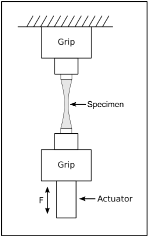
The axial fatigue testing machine in Fig. 3 applies uniform stress or strain to
the cross-section of the specimen. These machines are capable of tension and compression
loading fatigue tests.
2.2 Bending Fatigue Testing Machine

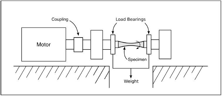
The bending fatigue machine shown in Fig. 4 is considered one of the most common types of machines used in fatigue testing. The test specimen is simultaneously subjected to bending and rotating by an apparatus connected to bearings. Therefore, it has the advantage that bending moment between loading locations is uniform, and it is free of shear stress.
2.3 Torsional Fatigue Testing Machine

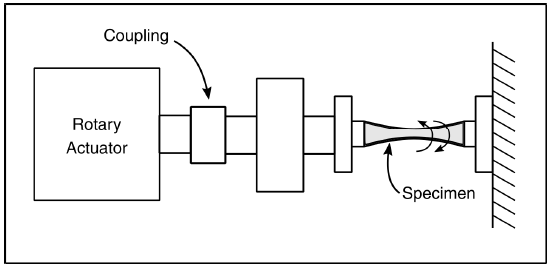
In this machine, one end of the specimen is fixed by a chuck and the other end is connected to a
rotary actuator therefore torsional stress can be applied to the sample.
2.4 Special Purpose Fatigue Testing Machine

Special-purpose fatigue testing machines are developed for specific components, such as; gears, bearings, wires etc. For example, Fig. 6 shows a special-purpose fatigue test machine for overhead line contact wires. In this design, the specimen was fixed on both sides with chucks and tensioned with weights. It was held in place by fixed rollers. An oscillating roller in the middle of the span provided a contact wire sample for bending. Since these three rollers involved single point contact, the contact wire was bent based on as three-point bending principles. These experimental configurations required 2-3 metre-length contact wire specimen.


