Submodeling is one of those “tricks” in stress analysis that used to be used all the time. But until recently it was a bit of a pain to do in ANSYS Mechanical so it fell out of use. Now, the process of doing submodeling is easy, efficient, and accurate. The purpose of this posting is to introduce the concept to newer users who have not used it before, and show experienced (old) users how much easier it is to do in ANSYS Mechanical vs. Mechanical APDL.
What is Submodeling?
Large-scale models such as; aircraft components, gear contact relations and giant equipment need a remarkably long solution time if you need to work with finest mesh properties. However, submodeling allow us to perform finite element analysis faster thanks to focusing on specific region. The basic idea is that you have a coarse model of your whole part or assembly. You ignore small features in the mesh that don’t have an impact on the overall response of the system – the local stiffness does not have influence on the strain beyond that local region. You then make a very refined model, the submodel, of the region of interest. You use the displacement field (and temperature if you have a temperature gradient) from the coarse model and apply it to the submodel as a boundary condition to get the accurate highly-refined response in the area of interest.


The Process
The process is fairly simple:
- Make and solve your full model
- Make a geometry model of the area you want a submodel in
- Attach the submodel to the engineering data and solution of the full model
- Set up and solve the submodel
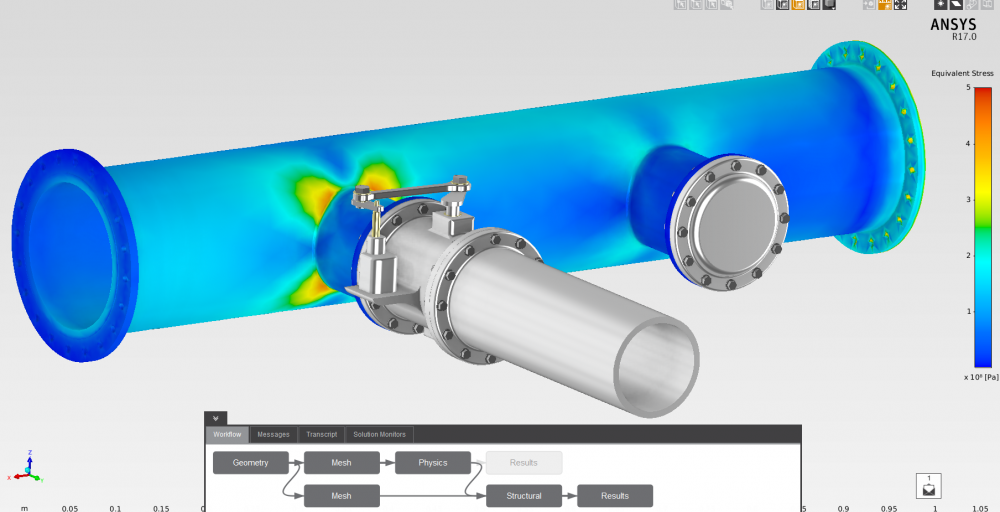
For the sample geometry we showed above, the system looks like this:
When you go into ANSYS Mechanical for the sample model, you have a new model branch:
When you first get in there, the branch is empty, you have to insert Body Temperature and/or Displacement:
The Details for the Displacement object are as follows:
There are a lot of options here. It is basically using the external load mapper to map the displacements. Consult the help and just play around with the options to understand them better. In most cases, all you need to do is specify the faces that you want the displacement field applied to for the Scope section.
A cool feature is that once you have specified the faces, you can “Import Load” and then view them by clicking on the object. Graphics Control –>Data = All shows vectors. Total/X/Y/Z shows the applied displacement field as a contour:
Now you just need to make sure your Submodel is set up correctly, you have the mesh you want, and any other loads that are applied directly to the Submodel are the same as the loads in the full model Run and you get your refined results.
Source : padtinc


