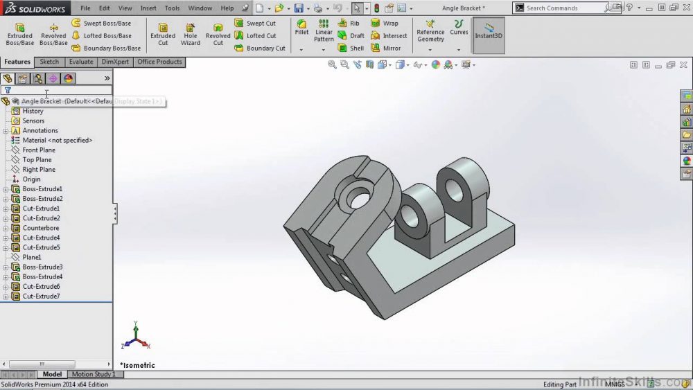
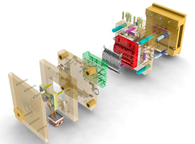
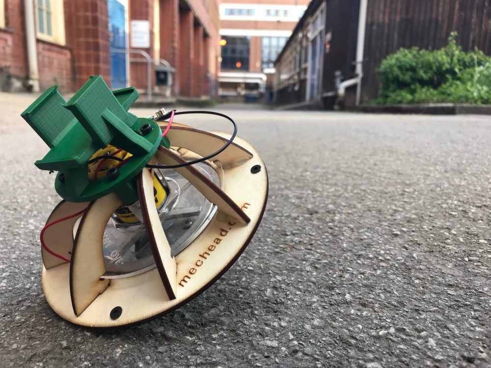
Graphics Systems would like to share their top 10 blog posts featuring tips and tricks in the SOLIDWORKS Suite.
10. View Mates Command “Secret” : Select Multiple Parts in SOLIDWORKS
How do you view the mates for a group of components? The answer: the standard View Mates, because you can select more than one part for that command!
Hold the CTRL key and select both parts together. (You can keep picking more parts if you want to.) When you’ve picked the last one you want, choose View Mates from the pop-up toolbar as shown:
Now you’ll see only the components you directly selected (in this case, the motor and the motor bracket) and any other parts that are mated to the selected parts. Also, the mates involving both selected parts will show in a box for editing, as usual with View Mates. Read the full article here.
9. Customize Wire Numbers with SOLIDWORKS Electrical
One of the many benefits of SOLIDWORKS Electrical is the ability to customize a vast number of elements to fit your particular electrical schematic design needs. Let’s talk about how to customize the Equipotential and Wire Numbers. In the following example, the Wire Number will be changed to coincide with the row in which they originate. This formula can be changed to fit design needs, this is just an example. Continue reading here.
8. SOLIDWORKS Simulation: Design Study? More Like Convergence Analysis
I’m going to show how to use the plots from design studies in SOLIDWORKS Simulation in order to perform a convergence analysis.. If the mesh is not fine enough, the problem is poorly represented. To ensure that the calculated values are independent of the mesh size, start with a coarse mesh and refine it. Look for changes in values along the way. Read the full article here.
7. A Basketball Motion Study in SOLIDWORKS
Learn how to make the perfect basket using Motion Simulation in SOLIDWORKS! By using a design study, we can measure the velocity applied to the basketball and make the perfect shot!
6. SOLIDWORKS Simulation: Behind the Software with Vibration Analysis
Vibration is one of the key factors in engineering design that is so important to consider when designing components that see that type of loading. As I’m sure you all well know, every structure has its own natural (resonant) frequencies that correspond to a particular motion (mode shape) of the structure. The majority of the time, designers want to avoid operating their components at these frequencies in order to prevent disaster…wouldn’t want another “Galloping Gertie” on our hands!
Let’s take a look at a simple vibration problem. Most of the systems we work with can be modeled as spring/mass systems. This example will show the process that most simulation software uses when solving for resonant frequencies and mode shapes. Below is the simple 2 degree of freedom system that we’ll be working with. Read the full article here.
5. Animating Rotary Motion in SOLIDWORKS
“Easy,” you said. You needed an animated motion study within which a component needed to rotate 360 degrees, or some multiple thereof. “I’ll just set a key point at the desired ending position, and then rotate the component. SOLIDWORKS’ transpositional animation will do just what I need.”
But it doesn’t seem to. In replaying your animation, the part doesn’t seem to have rotated at all. It’s not that the part didn’t move, per se – it did. Right back into the same position. SOLIDWORKS will calculate the shortest distance between two key points. Which, in this case, is? None. In another example, a part that was to rotate 270 degrees has instead just rotated 90…in the wrong direction! What’s an animator to do?
We have not one but two answers for you! Finish reading here.
4. SOLIDWORKS: Replace Components Without Mate Errors
What is the cause of the mate errors and how can we control them?
What’s happening here is that in order to rebuild a mate, SOLIDWORKS has to know which faces or edges are being referenced by the mate. To do that, the software creates IDs for each surface and edge as you build your model. These IDs are very difficult to control, and can vary by something as simple as adding sketch features in a different order. If the software cannot find the correct reference (such as when we replace components or delete features that are used for mating), that’s when we get the rebuild error.
We can help prevent this problem using one of the following three techniques:
1. Don’t create replacement components from scratch.
2. Use Datum Geometry (Planes or Axes… NOT Temporary Axes) for your mates.
3. Use Named Entities.
3. SOLIDWORKS, The Basics – Overriding Dimension Text
One of the most basic needs at times is the ability to override dimension text when working on a catalog, charted or otherwise tabulated drawing. Fortunately, the process is simple. When selecting a dimension, you will see a <DIM> variable in the Dimension Text field of the Dimension Property Manager. Think of that variable as an internal placeholder for the parametric model value. Simply replace that textstring with the desired text. Read the full article here.
2. SOLIDWORKS: What Makes a Golf Ball?
This all started when a colleague of mine made the innocent suggestion that I create the dimples on a golf ball for my next blog. Well me not having the forethought to think through the consequences of this, I agreed! After hours of contemplating how I was going to do this, I finally came up with an idea that seemed to work. Many of the golf balls out there use an octahedral dimple design. This meant that I could break the ball up into 8th’s and only create the dimples on a small section and then mirror the rest. The main challenge I found was dealing with the change in orientation of every dimple. It was easy enough to create one dimple with a cut revolve but when you tried to pattern that cut, it would not change the orientation to be normal to the outside surface. To get around this, I used a base revolve that intersected the golf ball by the amount needed to create the dimple. In order for this approach to work for all the dimples, I needed a construction surface that split the center of each revolve. Finish reading here.
1. SOLIDWORKS 2015: A Few Of My Favorite Things
I’ve been asked to highlight three of my favorite new things in SOLIDWORKS 2015. It’s not easy for me to pick out just three, but in terms of everyday impact — stuff that makes me smile and that I miss when I’m using an older version — this is my (very short) list.
Selection enhancements: There are two aspects to some seriously useful enhancements to selecting items in SOLIDWORKS 2015. First and foremost, you can “Select Previous” with a click of the pop-up toolbar. An adjunct of the Select Previous function is the ability to save your selection sets for future use.
Cut list naming and updating: In SOLIDWORKS 2015, Automatic Update means exactly what it says — no more right-clicking and updating the cut list yourself (although you can still do it that way if you like).
Asymmetric fillets: This is a really easy way to get some complex rounds on your model without a lot of fuss.
Source: http://blogs.solidworks.com/tech/2015/01/top-10-tips-and-tricks-in-the-solidworks-suite.html


