When performing structural finite element analysis (FEA), there are three types of nonlinearities that the analyst needs to consider including in their simulation. Material nonlinearities are needed to predict plastic strains in metallic parts, cracking or crushing of concrete, or extreme deformation of plastic or rubber materials. Contact nonlinearities are required to predict change in status and/or sliding friction between assembly parts. The third option, geometric nonlinearity, involves a few different concepts and it is not always easy to identify when it is required.
Before I explain any further, the thing you should note if you are an ANSYS Mechanical simulation user is this: If you don’t know if you need large deflection or not, you should turn it on. There is really no way to know for certain if it’s needed or not unless you perform a comparison study with and without it.
So, what are large deflection effects? In simple terms, the inclusion of large deflection means that ANSYS accounts for changes in stiffness due to changes in the shape of the parts you are simulating. The classic case to consider is the loaded fishing rod.

In its undeflected state, the fishing rod is very flexible at the tip. With a heavy fish on the end of the line, the rod deflects downward and it is then easy to observe that the stiffness of the rod has increased. In other words, when the rod is lightly loaded, a small amount of force will cause a certain downward deflection at the top. When the rod is heavily loaded, however, a much larger amount of force will be needed to cause the tip to deflect downward by the same amount.
This change in the force amount required to achieve the same change in displacement implies that we do not have a linear relationship between force and displacement.
Consider Hooke’s law, also known as the spring equation:
F = Kx
Where F is the force applied, K is the stiffness of the structure, and x is the deflection. In a linear system, doubling the force results in double the displacement. In our fishing rod case, though, we have a nonlinear system. We might need to triple the force to double the displacement, depending on how much the rod is loaded relative to its size and other properties, and then to double the displacement again we might need to apply four times that force, just using numbers out of my head as examples.
So, in the case of the fishing rod, Hooke’s law in a linear form does not apply. In order to capture the nonlinear effect we need a way for the stiffness to change as the shape of the rod changes. In our finite element solution in ANSYS, it means that we want to recalculate the stiffness as the structure deflects.
This recalculation of the stiffness as the structure deflects is activated by turning on large deflection effects. Without large deflection turned on, we are constrained to using the linear equation, and no matter how much the structure deflects we are still using the original stiffness.
So, why not just have large deflection on by default and use it all the time? My understanding is that since large deflection adds computation expense to have it on, it’s off by default. It’s the same as for a lot of advanced usage, such as frictionless or frictional contact vs. the default bonded (simpler) behavior. In other words, turning on large deflection will trigger a nonlinear solution, meaning multiple passes through the solver using the Newton Raphson method instead of the single pass needed for a linear problem.
Here is an example of a simplified fishing rod. The image shows the undeflected rod (top), which is held fixed on the left side and has a downward force load applied on the right end. The bottom image shows the final deflected shape, with large deflection effects included. The deflection at the tip in this case is 34 inches.
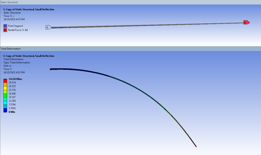 In comparison running the same load with large deflection turned off resulted in a tip deflection of 40 inches. Thus, the calculated tip deflection is 15% less with large deflection turned on, since we are now accounting for change in stiffness with change in shape as the rod deflects.
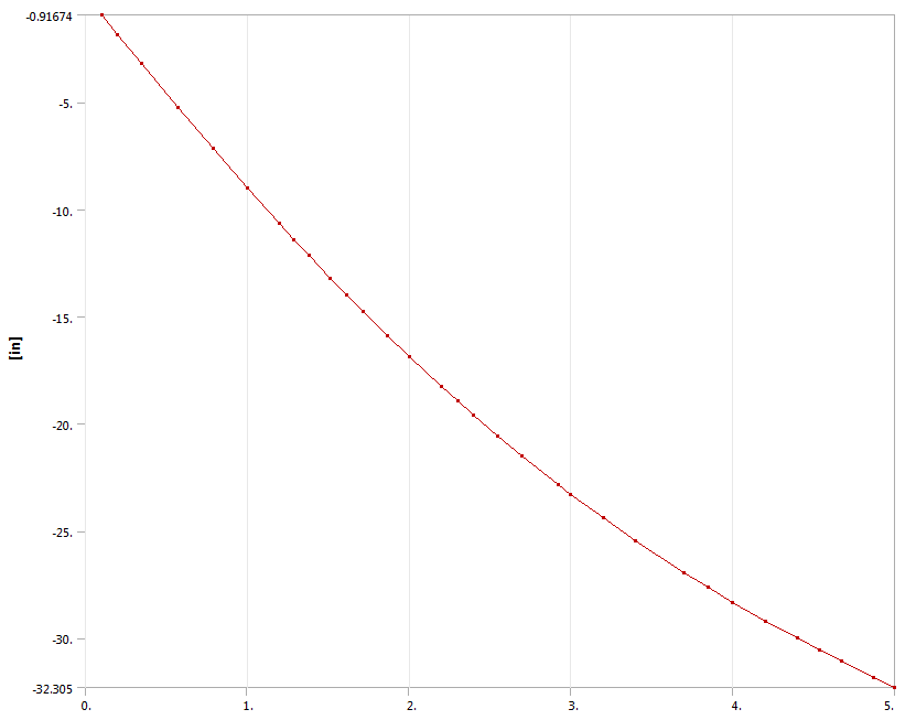
Below we have a force (horizontal axis) vs. deflection (vertical axis) plot for a nonlinear simulation of a fishing rod with large deflection turned on. The fact that the curve is not a straight line confirms that this is a nonlinear problem, with the stiffness (slope of the curve) not constant. We can also see that as the force gets higher, the slope of the curve is more horizontal, meaning that more force is needed for each incremental amount of displacement. This matches our observations of the fishing rod behavior.
 So, getting back to our original point, it’s often the case that we don’t know if we need to include large deflection effects or not. When in doubt, run cases with and without. If you don’t see a change in your key results, you can probably do without large deflection.
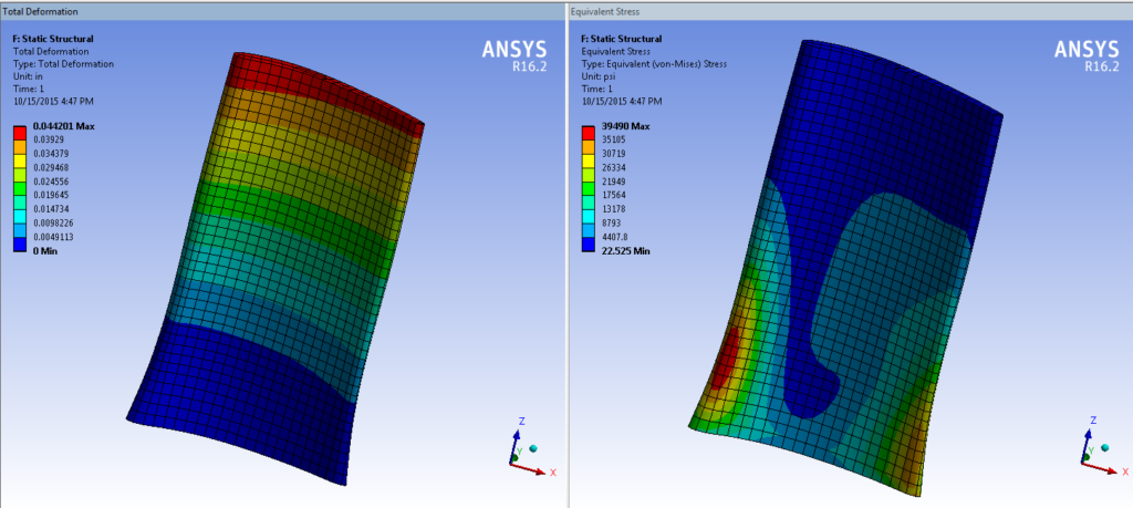
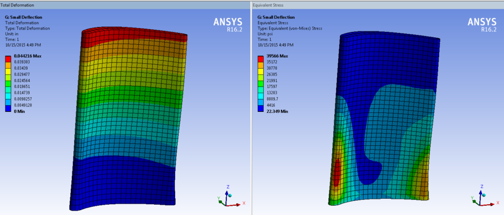
Here is an example using an idealized compressor vane. In this case, the deflections and stresses with and without large deflection effects are nearly the same (the stress difference is about 0.2%).
Large Deflection On:
 Small Deflection:
 Bottom line: when in doubt, try it out, with and without large deflection. In ANSYS Mechanical, Large Deflection effects are turned on or off in the details of the Analysis Settings branch.
It’s worth noting that turning on large deflection in ANSYS actually activates four different behaviours, known as large deflection which include large rotation, large strain, stress stiffening, and spin softening. All of these involve change in stiffness due to deformation in one way or another.
Sources
padtinc.com


